By Dr. Thomas Burnell and Dr. Bethany Turner
Next Lesson - Electrocardiogram Pathology
Abstract
- There are 10 different electrodes that are placed on the body to produce an ECG, 4 limb and 6 chest.
- The phases of electrical conduction correspond to changes on the ECG: P wave - atrial depolarisation, QRS complex - ventricular depolarisation, and T wave - ventricular repolarisation.
- Changes in the timings between different ECG signals can indicate pathology - PR, QRS and QT intervals.
Core
Here is a brief recap of the conduction system, which is explained in more detail in the Cardiac Cycle article.
- SA node sends an action potential (AP) which spreads across atria causing contraction.
- The AP reaches the AV node, which transmits the AP to the Bundle of His.
- The Bundle of His transmits APs down the left and right bundle branches to Purkinje fibres.
- The impulse conducts across the ventricular myocardium causing contraction.
The signals sent throughout the heart by the conduction system can be picked up on an electrocardiograph (ECG). In this article the word ‘electrode’ will be used to describe the wires you place on the body, and the word ‘lead’ to describe the views of the heart, and the recordings on the ECG.
When recording an ECG, 10 electrodes are placed on the patient's body to give 12 views of the heart:
- 4 limb electrodes which are placed on bony parts e.g. wrists and ankles:
- Right arm - Red electrode
- Left arm - Yellow electrode
- Left leg - Green electrode
- Right leg - Black electrode
This placement can helpfully be remembered by the acronym Ride Your Green Bike when starting from the right wrist and working clockwise when looking at the front of the patient.
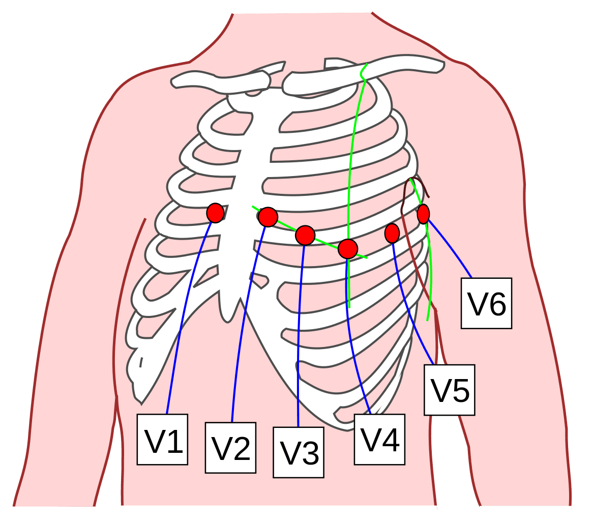
- 6 chest electrodes. Each of these gives its own lead/view of the heart. V1-V6 which are placed across the chest in specific positions:
- V1 - right sternal edge, 4th intercostal space (ICS)
- V2 - left sternal edge, 4th ICS
- V3 - halfway between V2 and V4
- V4 - mid-clavicular line, 5th ICS
- V5 - halfway between V4 and V6
- V6 - mid-axillary line in line with V4
To find the 4th intercostal space (ICS), first find the sternal angle (the slight dip that can be felt when feeling between the manubrium and body of the sternum). The angle lies next to the 2nd ICS, so if you move your fingers across from the sternal angle, you should feel a dip which is the 2nd ICS. From there simply count down two spaces to reach the 4th ICS.
It is usually best to place leads V1, V2, V4 and V6 first to help with placement of V3 and V5

Diagram - The location of where the chest electrodes should be placed
Creative commons source by JMarchN [CC BY-SA 3.0 (https://creativecommons.org/licenses/by-sa/3.0)]
The multiple leads give us different views of the heart and allow us to see where pathology is. This is important in myocardial infarctions in order to deduce which coronary artery is affected.
Each lead/view of an ECG looks at a different part of the heart and is associated with a coronary artery:

Diagram - Coronary arteries and their corresponding ECG lead
SimpleMed original by Dr. Thomas Burnell
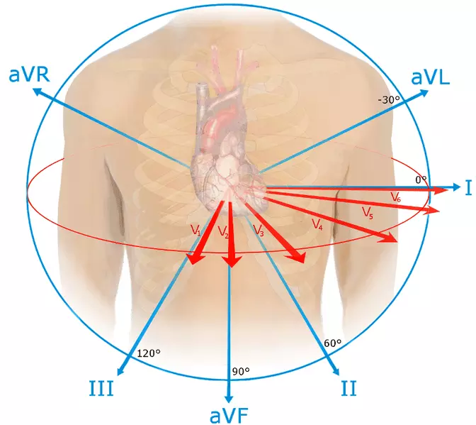
Leads V1 to V6 are known as the anterior leads, meaning that they look at the front of the heart. More specifically, V1 and V2 look at the right ventricle and interventricular septum, V3 and V4 look at the anterior surface of the ventricles, and V5 and V6 look at part of the left ventricle. These views can be remembered by thinking about where the electrodes are placed on the patient.
Leads II, III and aVF are the inferior leads and look at the bottom part of the left ventricle.
Leads I, aVL, V5 and V6 are the lateral leads, and look at the side of the left ventricle.

Diagram - The view that each lead 'sees' the heart. With this diagram you can see how the leads can localise pathology to certain regions of the heart
Creative commons source by Npatchett [CC BY-SA 4.0 (https://creativecommons.org/licenses/by-sa/4.0)]
Electrodes on the body look at the flow of current in the heart, and whether the electrical activity of the heart is going towards or away from the electrode. This gives us either an upward or downward deflection. This concept is best thought about in the context of the cardiac conduction pathway.
- Depolarisation towards the electrode is seen as an upward deflection, e.g. when the impulse is travelling down the septum, this gives the upwards part of the QRS complex.
- Depolarisation away from the electrode is seen as a downward deflection, e.g. when the impulse is travelling up the ventricles, this gives the downwards part of the QRS complex.
- Repolarisation towards the electrode is seen as a downward deflection.
- Repolarisation away from the electrode is seen as an upward deflection.
How the Conduction System looks on an ECG
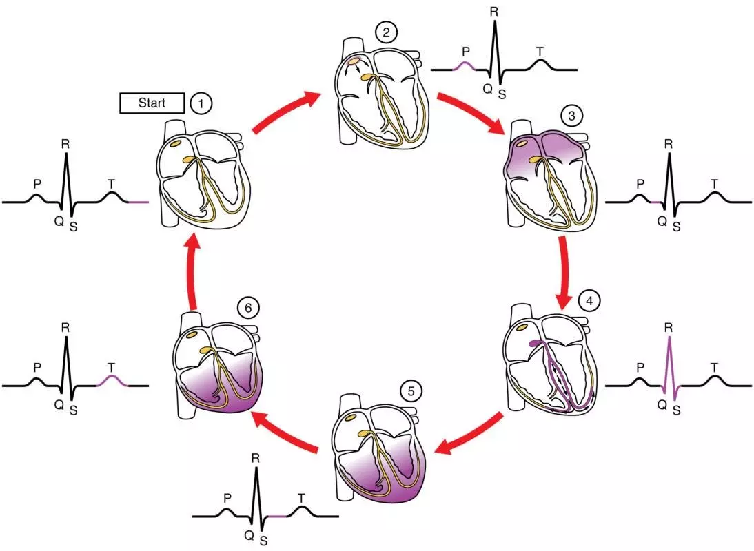
When talking about how the conduction looks on an ECG normally, we imagine the positive electrode is at the apex of the heart. This gives us the lead II view of the heart on an ECG.

Diagram - The changes in the ECG during heart contraction
Creative commons source by OpenStax College [CC BY-SA 3.0 (https://creativecommons.org/licenses/by-sa/3.0)]
- Before atrial depolarisation, the SA node depolarises but the signal is not enough to register on an ECG so it appears as an isoelectric segment (flat line).
- Then there is atrial depolarisation which appears as an upward deflection as depolarisation spreads towards the electrode. This is the P wave.
- The impulse reaches the AV node and is delayed after atrial depolarisation. This appears as another isoelectric segment.
- The impulse spreads to the ventricles, and ventricular depolarisation is now seen as the QRS complex.
- The depolarisation of the septum happens from right to left. This is seen as a downward deflection as it is away from the electrode, which is the Q aspect of the QRS complex.
- This is followed by an upwards deflection (R wave) as the depolarisation spreads down the bundle of His.
- The negative deflection is the S wave and is the wave of depolarisation spreading up the walls of the ventricles via the purkinje fibres away from the positive electrode.
- There is then an isoelectric segment once ventricular depolarisation is complete.
- Finally ventricular repolarisation occurs which is seen as the T wave.
An additional U wave can sometimes been seen in an ECG. It may be a normal finding, but prominent U waves can be associated with pathology, e.g. hypokalaemia.

Diagram - A normal ECG
SimpleMed original by Dr. Bethany Turner
When reading an ECG, each small box is equal to 0.04 seconds while each large box is equal to 0.20 seconds (there are 5 small boxes in the length of one large box).
An easy way to calculate a patient's HR using an ECG is:
- Count the number of large boxes between two R waves (count any small boxes as 0.2 of a large box).
- Then calculate 300/(number of large boxes) which will give the heart rate.
If the patient has an irregular rhythm then the above method will not work as you will get different values depending on which heart beats you use. The following alternative method can be used to calculate the average heart rate:
- Look at lead II on the bottom of the ECG (pacing strip).
- Count how many times a QRS complex occurs in 30 large squares - 30 large squares is 6 seconds.
- Multiply the number of complexes by 10 to give you the HR.
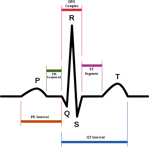
PR interval - interval between the start of the P wave and the start of the QRS complex. It is normally 3-5 small boxes. >1 large box is prolonged.
- A prolonged PR interval suggests delayed conduction through the AV node. This can be seen in:
- Heart block
- Ischaemic heart disease
- Hypokalaemia
- A shortened PR interval suggests that the delay at the AV node has not happened. This can be seen in:
- Wolff-Parkinson-White syndrome (there is a faster conduction pathway between the atria and ventricles)
QRS interval - length of the QRS complex (start of the Q wave to the end of the S). It is normally 2-3 small boxes.
- A widened QRS interval suggests that depolarisation is arising ectopically in the ventricles. This means that the wave of depolarisation does not spread via the His-Purkinje system so it takes longer for the wave to spread along the walls of the ventricles. Can be seen in:
- Bundle branch block
- Hyperkalaemia
- Ventricular ectopics
QT interval - interval between the start of the Q wave and the end of the T wave. It is normally 10-12 small boxes. This value varies with heart rate, therefore readings need to be standardised before values can be compared.
- Prolonged QT interval suggests delayed ventricular repolarisation. Can be seen in:
- Use of certain drugs e.g. amioderone and tricyclic antidepressants.

Diagram - The intervals seen in an ECG
Creative commons source by Agateller (Anthony Atkielski), converted to svg by atom. [Public domain]
Sinus rhythm is a normal heart rhythm originating from the sinoatrial node. It is characterised by:
- A regular rhythm
- HR of 60-100 bpm
- P waves seen
- P waves upright in leads I and II
- Normal PR interval
- Every P wave followed by a QRS
- Every QRS preceded by a P wave
- Normal QRS width
Patients can still have a sinus rhythm despite being bradycardic or tachycardic. In these circumstances, they would have sinus bradycardia or sinus tachycardia.
When confronted with an ECG, it's good to have a system in your head that you can use to analyse the ECG and describe it. The following is a suggested order for looking at different aspects of the rhythm strip of an ECG.
- Calculate the heart rate.
- Is the rhythm regular or irregular? This can be hard to determine in faster heart rates, so a good technique is to mark the distance between two or three tips of QRS complexes on a piece of paper and slide it across the rhythm strip. If the marks align, then the rhythm is regular.
- Are there P waves? This suggests atrial activity.
- Are there QRS complexes? This suggests ventricular activity.
- Is each P wave followed by a QRS complex, and each QRS complex preceded by a P wave?
- Measure the intervals: PR interval, QRS width, QT interval.
If all of these observations are normal, then the patient has a sinus rhythm, if one or more aspects are abnormal, then this suggests some sort of pathology.
Edited by: Dr. Ben Appleby
Reviewed by: Dr. Marcus Judge
- 24375

